UNIT-1
CHARACTERISTIC OF CONVENTIONAL MACHINING PROCESS
- In conventional machining process the ability of cutting tool is utilized to stress the materials beyond the yield point to start the material removal process.
- In conventional machining cutting tool must be harder than the work piece material.
- The advent of hard materials for aerospace applications have made the machining process by conventional methods very difficult and time consuming. This is due to Material Removal Rate (MRR) decreases with increased hardness of the work material.
Non Traditional Machining (NTM) Processes on the
other
hand are characterised as follows:
• Material removal may occur
with chip formation or even no chip formation may take place.
• In NTM, there may not be a
physical tool present. For example in laser jet machining, machining is carried
out by laser beam. However in Electrochemical Machining there is a physical
tool that is very much required for machining
• In NTM, the tool need not
be harder than the work piece material. For example, in EDM, copper is used as
the tool material to machine hardened steels.
• Mostly NTM processes do not
necessarily use mechanical energy to provide material removal. They use
different energy domains to provide machining. For example, in USM, AJM, WJM
mechanical energy is used to machine material, whereas in ECM electrochemical
dissolution constitutes material removal.
Classification of unconventional machining process:
Classification of unconventional machining processes was mainly on the basis of the nature of energy employed in machining process. They are
1. Chemical Processes
- Chemical Machining (CM)
- Photochemical Machining (PCM)
2. Electrochemical Processes
- Electro-Chemical Machining (ECM)
- Electro Chemical Grinding (ECG)
3. Electro-Thermal Processes
- Electrical Discharge Machining (EDM)
- Electron Beam machining (EBM)
- Plasma Arc Machining (PAM)
- Laser Beam Machining (LBM)
4. Mechanical Processes
- Ultrasonic Machining (USM)
- Abrasive Jet Machining (AJM)
- Water Jet Machining (WJM)
- Abrasive Water jet Machining (AWJM)
NEED OF UNCONVENTIONAL MACHINING PROCESS:
• Intricate shaped blind hole
– e.g. square hole of 15 mmx15 mm with a depth of 30 mm
• Difficult to machine
material – e.g. same example as above in Inconel, Ti-alloys or carbides.
• Low Stress Grinding –
Electrochemical Grinding is preferred as compared to conventional grinding
• Deep hole with small hole diameter – e.g. φ 1.5
mm hole with l/d = 20
• Machining of composites.
Use the above mentioned link for pdf notes of first unit
UNIT-2
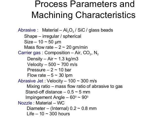
Abrasive Jet Machining
WORKING:
In Abrasive Jet
Machining (AJM), abrasive particles are made to impinge on the work material at
a high velocity. The jet of abrasive particles is carried by carrier gas or
air. The high velocity stream of abrasive is generated by converting the
pressure energy of the carrier gas or air to its kinetic energy and hence high
velocity jet. The nozzle directs the abrasive jet in a controlled manner onto
the work material, so that the distance between the nozzle and the work piece
and the impingement angle can be set desirably. The high velocity abrasive
particles remove the material by micro- cutting action as well as brittle fracture
of the work material.
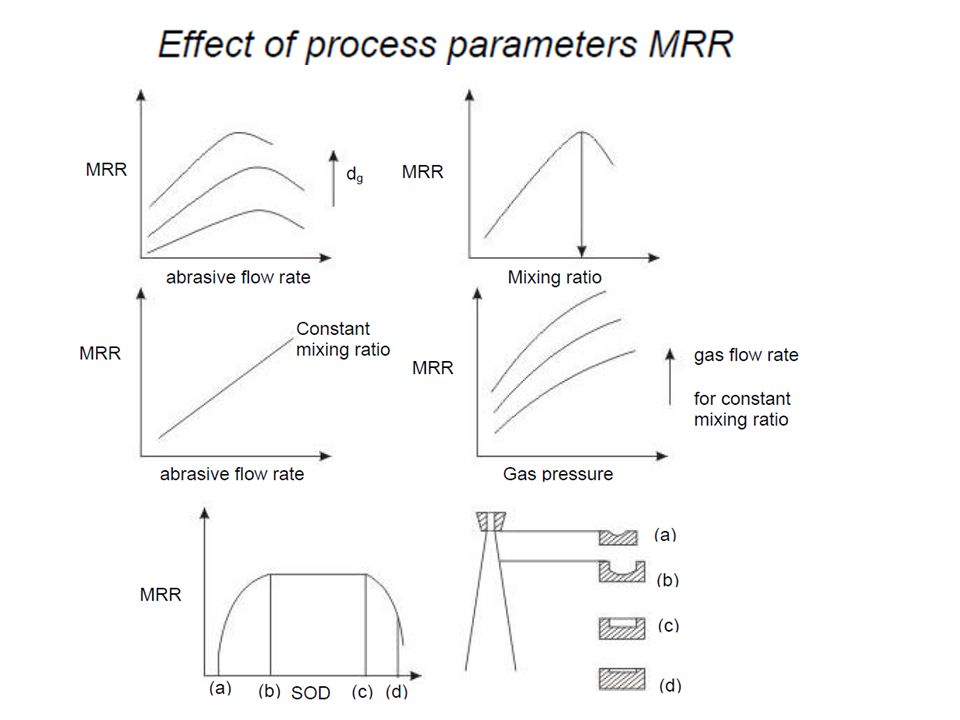
*PROCESS PARAMETER AND THERE GRAPH ARE
MOST IMPORTANT *
Applications:
• For drilling holes of intricate shapes in hard
and brittle materials
• For machining fragile, brittle and heat
sensitive materials
• AJM can be used for drilling, cutting, deburring, cleaning and etching.
• Micro-machining of brittle materials
AS FAR AS MODELLING IS CONCERN GO THROUGH THE CLASS NOTES
NEXT TOPIC- ULTRASONIC MACHINING
Definition:
Ultrasonic Machining is a non-traditional process, in which abrasives contained in a slurry are driven against the work by a tool oscillating at low amplitude (25-100 microns) and high frequency (15-30 kHz).
Process:
Ultrasonic machining is a mechanical type non-traditional machining process. It is employed to machine hard and brittle materials.In ultrasonic machining, tool of desired shape vibrates at ultrasonic frequency ( 19 to25 kHz. ) with an amplitude of 15-50 Microns over work piece. Generally tool is pressed down with a feed force F. Between the tool and work, machining zone is
flooded with hard abrasive particles generally in the form of water based slurry. As the tool vibrates over the work piece, abrasive particles acts as indenter and indent both work and tool material . Abrasive particles , as they indent , the work materialwould remove the material from both tool and work piece. In Ultrasonic machining material removal is due to crack initiation, propagation and brittle fracture of material. USM is used for machining hard and brittle materials, which are poor conductors of electricity and thus cannot be processed by Electrochemical machining
( ECM) or Electro discharge machining (EDM).

Equipment:
Ultrasonic Machining consists of :
1. High Power sine wave
generator
2. Magneto-strictive Transducer
3. Tool Holder
4. Tool
High power sine wave generator
This unit converts low frequency (60 Hz) electrical power to high frequency (20kHz) electrical power.
Transducer
The high frequency electrical signal is transmitted to traducer which converts it intohigh frequency low amplitude vibration. Essentially transducer converts electrical energy to mechanical vibration. There are two types of transducer used
1. Piezo electric transducer
2. Magneto-stricitve transducer.
Piezo electric transducer: These transducer generate a small electric current
when they are compressed. Also when the electric current is passed though
crystal it expands. When the current is removed , crystal attains its original size
and shape. Such transducers are available up to 900 Watts. Piezo electric crystals
have high conversion efficiency of 95%.
Magneto-strictive transducer: These also changes its length when subjected to
strong magnetic field. These transducer are made of nickel , nickel alloy sheets.
Their conversion efficiency is about 20-30%. Such transducers are available up to
2000 Watts. The maximum change in length can be achieved is about 25
micron
Tool holder. OR Horn.
The tool holder holds and connects the tool to the transducer. It virtually transmits
the energy and in some cases, amplifies the amplitude of vibration. Material of tool
should have good acoustic properties, high resistance to fatigue cracking. Due
measures should be taken to avoid ultrasonic welding between transducer and tool
holder. Commonly used tool holders are Monel, titanium, stainless steel
Tools are made of relatively ductile materials like Brass, Stainless steel or Mild steel
so that Tool wear rate (TWR) can be minimized. The value of ratio of TWR and MRR
depends on kind of abrasive, work material and tool materials
Process parameters
1. Amplitude of vibration ( 15 to 50 microns)
2. Frequency of vibration ( 19 to 25 kHz).
3. Feed force (F) related to tool dimensions
4. Feed pressure
5. Abrasive size
6. Abrasive materialAl203, SiC, B4C, Boron silicarbide, Diamond.
7. Flow strength of the work material
8. Flow strength of the tool material
9. Contact area of the tool
10.Volume concentration of abrasive in water slurry
11. Tool
a. Material of tool
b. Shape
c. Amplitude of vibration
d. Frequency of vibration
e. Strength developed in tool
12. Work material
a. Material
b. Impact strength
c. Surface fatigue strength
13.Slurry
a. Abrasive – hardness, size, shape and quantity of abrasive flow
b. Liquid – Chemical property, viscosity, flow rate
c. Pressure
d. Density
Machining characteristics:
Following are the USM process criteria
1. Material removal rate
2. Geometrical accuracy
3. surface finish
4. Out of roundness
Process criteria are generally influenced by the process parameters
The characteristics of above process parameters on process criteria are as follows:
1. Effect of amplitude on MRR Increase in amplitude of vibration increases MRR. To maximize the amplitude of vibration concentrator should operate at resonance
frequency. Under certain circumstances this limits also the
maximum size of abrasive to be used.
2. Effect of Frequency on MRRFrequency has significant effect on MRR.Frequency used for machining process must
be resonant frequency to obtain the greatestamplitude at the tool tip and thus achieve themaximum utilization of the acoustic system.
3. Effect of abrasive grain size An increase in abrasive grain size results in higher MRR but poorer surfacefinish.Maximum MRR is achieved when abrasivegrain size is comparable with amplitude ofvibration of the tool. Hardness of theabrasives and method of introducing the slurry has also effect on MRR.
4. Effect of Applied static load(Feed force).MRR increase with the feed force. MaximumMRR depends on the amplitude of vibrations.Surface finish is found to be little affected bythe applied static load. Higher loads, contraryto expections, do not give give a rougherfinish. Surface finish, Infact,improves because the grains are crushed to small size with higher loads.
5 Effect of Slurry, Tool and Work Material.
MRR increases with slurry
concentration. Slurry saturation occurs at
30 to 40% abrasive/water mixture.
Material Removal rate drops with
increasing viscosity.
The pressure with which the slurry is
fed into the cutting zone affects MRR . In
some cases MRR can be increased even ten
times by supplying the slurry at increased
pressure.
The shape of the tool affects the
MRR. Narrower rectangular tool gives more
MRR compared to square cross section
*PROCESS PARAMETER AND THERE GRAPH ARE MOST IMPORTANT *
Applications:
1. Machining of cavities in electrically non-conductive ceramics
2. Used to machine fragile components in which otherwise the scrap rate is high
3. Used for multistep processing for fabricating silicon nitride (Si3N4) turbine blades
4. Large number of holes of small diameter. 930 holes with 0.32mm has been
reported ( Benedict, 1973) using hypodermic needles
5. Used for machining hard, brittle metallic alloys, semiconductors, glass, ceramics,
carbides etc.
AS FAR AS MODELLING IS CONCERN GO THROUGH THE CLASS NOTES
NEXT TOPIC -ELECTROCHEMICAL MACHINING
Electrochemical machining (ECM) is a machining process in which electrochemical process is used to remove materials from the workpiece. In the process, workpiece is taken as anode and tool is taken as cathode. The two electrodes workpiece and tool is immersed in an electrolyte (such as NaCl). When the voltage is applied across the two electrodes, the material removal from the workpiece starts. The workpiece and tool is placed very close to each other without touching. In ECM the material removal takes place at atomic level so it produces a mirror finish surface.
Working Principle:

ECM working is opposite to the electrochemical or galvanic coating or deposition process.
During electrochemical machining process, the reactions take place at the electrodes i.e. at the anode (workpiece) and cathode (tool) and within the electrolyte.
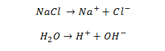
Let’s take an example of machining low carbon steel which is mainly composed of ferrous alloys (Fe). We generally use neutral salt solution of sodium chloride (NaCl) as the electrolyte to machine ferrous alloys. The ionic dissociation of NaCl and water takes place in the electrolyte as shown below.
As the potential difference is applied across the electrode, the movement of ions starts in between the tool and w/p. The positive ions moves towards the tool (cathode) and negative ions move towards the workpiece.
At cathode the hydrogen ions takes electrons and gets converted into hydrogen gas.
In the same way the iron atoms comes out from the anode (w/p) as Fe++ ions.
Within the Electrolyte, the sodium ions combines with Hydroxyl ions and form sodium hydroxide and ferrous ion combine with Chloride ions and forms ferrous chloride. Also iron ions combine with hydroxyl ions and forms Iron hydroxide.
In the electrolyte the FeCl2 and Fe(OH)2 produced and gets precipitated in the form of sludge and settle down. In this way material is removed from the workpiece as sludge.
Main Equipment of ECM:
- Power Supply
- Electrolyte filtration and delivery system
- Tool Feed system
- Working Tank
Application
- The ECM process is used for die sinking operation, profiling and contouring, drilling, grinding, trepanning and micro machining.
- It is used for machining steam turbine blades within closed limits.
UNIT -5
HIGH ENERGY RATE FORMING PROCESSES-In these forming processes large amount of energy is applied for a very short interval of time. Many metals tend to deform more readily under extra – fast application of load which make these processes useful to form large size parts out of most metals including those which are otherwise difficult – to – form.
There are three main high energy rate forming processes:
a) explosive forming
b) magnetic forming
c) electro hydraulic forming
EXPLOSIVE FORMING
a) Explosive forming is distinguished from conventional forming in that the punch or diaphragm is replaced by an explosive charge. The explosives used are generally high – explosive chemicals, gaseous mixtures, or propellants.There are two techniques of high – explosive forming:
a) stand – off technique
b) the contact technique.
a) Standoff Technique-The sheet metal work piece blank is clamped over a die and the assembly is lowered into a tank filled with water. The air in the die is pumped out. The explosive charge is placed at some predetermined distance from the work piece, see . On detonation of the explosive, a pressure pulse of very high intensity is produced. A gas bubble is also produced which expands spherically and then collapses. When the pressure pulse impinges against the work piece, the metal is deformed into the die with as high velocity as 120 m/s.
left hand side diagram is for a) stand off technique right hand side a) contact technique
application of contact technique a) The process has been successfully used to form steel plates 25 mm thick x 4 m diameter and to bulge steel tubes as thick as 25 mm.
b) the contact technique -The explosive charge in the form of cartridge is held in direct contact with the work piece while the detonation is initiated. The detonation builds up extremely high pressures (upto 30,000MPa) on the surface of the work piece resulting in metal deformation, and possible fracture. The process is used often for bulging tubes.
Applications- Explosive forming is mainly used in the aerospace industries but has also found successful applications in the production of automotive related components. The process has the greatest potential in limited – production prototype forming and for forming large size components for which conventional tooling costs are prohibitively high.
magnetic forming(Magnetic Pulse Forming)
b ) Magnetic forming-The process is also called magnetic pulse forming and is mainly used for swaging type operations, such as fastening fittings on the ends of tubes and crimping terminal ends of cables.
Principle of magnetic forming- To illustrate the principle of electromagnetic forming, consider a tubular work piece. This work piece is placed in or near a coil, A high charging voltage is supplied for a short time to a bank of capacitors connected in parallel. (The amount of electrical energy stored in the bank can be increased either by adding capacitors to the bank or by increasing the voltage). When the charging is complete, which takes very little time, a high voltage switch triggers the stored electrical energy through the coil. A high – intensity magnetic field is established which induces eddy currents into the conductive work piece, resulting in the establishment of another magnetic field. The forces produced by the two magnetic fields oppose each other with the consequence that there is a repelling force between the coil and the tubular work piece that causes permanent deformation of the work piece.
Applications
Electromagnetic forming process is capable of a wide variety of forming and assembly operations. It has found extensive applications in the fabrication of hollow, non – circular, or asymmetrical shapes from tubular stock.
Electro hydraulic forming
Electro hydraulic forming (EHF) -also known as electro spark forming, is a process in which electrical energy is converted into mechanical energy for the forming of metallic parts. A bank of capacitors is first charged to a high voltage and then discharged across a wire between two electrodes, causing explosions inside the hollow work piece, which is filled with some suitable medium, generally water. These explosions produce shock waves that travel radially in all directions at high velocity until they meet some obstruction. If the discharge energy is sufficiently high, the hollow work piece is deformed. The deformation can be controlled by applying external restraints in the form of die or by varying the amount of energy released . Electro hydraulic forming can be done with and without wire.
APPLICATION OF EHF
Materials having low ductility or having critical impact velocity less than 30 m/s are generally not considered to be good candidate for EHF. All materials that can be formed by conventional forming processes can be formed by EHF also
UNIT -3
Laser Beam Machining (LBM) is a form of machining process in which laser beam is used for the machining of metallic and non-metallic materials. In this process, a laser beam of high energy is made to strike on the workpiece, the thermal energy of the laser gets transferred to the surface of the w/p (workpiece). The heat so produced at the surface heats, melts and vaporizes the materials from the w/p.Light amplification by stimulated emission of radiation is called LASER.
Working Principle
It works on the principle that when a high energy laser beam strikes the surface of the workpiece. The heat energy contained by the laser beam gets transferred to the surface of the w/p. This heat energy absorbed by the surface heat melts and vaporizes the material from the w/p. In this way the machining of material takes place by the use of laser beam.
How Laser Beam is Produced
Stimulated Emission
In normal condition, the electrons present in atoms lies in the ground state (lowest energy level). When some source of energy is provided to the atoms in the form of radiation, the electrons of the atoms absorbs energy and excited to higher energy level. After a short duration, these electrons automatically jump back to the ground state and while doing so they emit photons of light. This emission of photons by the electrons is called spontaneous emission.
When the electrons in the excited state do not jumps back to the ground state by its own. This situation is called meta-stable state. When a photon is fired to the meta- stable state of atoms, this stimulates an electron at excited state and it jumps back to its ground state giving of two photons (one photon that we fired and other produced by the electron). These two photons stimulate other atoms electrons and produces more photons- a chain reactions starts and number of photon increases. This process is called stimulated emission as we are stimulating other electrons to get photons. Here we are getting two light photons from a single photon i.e. amplifying the light (increasing the light).
Hence the light beams produced by this method is called laser (light amplification by stimulated emission of radiation).
Types of Laser
On the basis of the media used for the production of the laser it is classified as
1. Gas Lasers: In these types of laser, gases are used as the medium to produce lasers. The commonly used gases are He-Ne, argon and Co2.
2. Solid State Lasers: The media of the solid state lasers are produced by doping a rare element into a host material.
Ruby laser is an example of solid state laser in which ruby crystal is used as medium for the generation of laser beam.
Main Parts
The various main parts used in the laser beam machining are
1. A pumping Medium: A medium is needed that contains a large number of atoms. The atoms of the media are used to produce lasers.
2. Flash Tube/Flash Lamp: The flash tube or flash lamp is used to provide the necessary energy to the atoms to excite their electrons.
3. Power Supply: A high voltage power source is used to produce light in flashlight tubes.
4. Capacitor: Capacitor is used to operate the laser beam machine at pulse mode.
5. Reflecting Mirror: Two types of mirror are used, first one is 100 % reflecting and other is partially reflecting. 100 % reflecting mirror is kept at one end and partially reflecting mirror is at the other end. The laser beams comes out from that side where partially reflecting mirror is kept
Working of Laser Beam Machining
A very high energy laser beam is produced by the laser machines. This laser beam produced is focused on the workpiece to be machined.When the laser beam strikes the surface of the w/p, the thermal energy of the laser beam is transferred to the surface of the w/p. this heats, melts, vaporizes and finally removes the material form the workpiece. In this way laser beam machining works.
Advantages
It produces a very high amount of energy, about 100 MW per square mm of area.
It is capable of producing very accurately placed holes.
Laser beam machining has the ability to cut or engrave almost all types of materials, when traditional machining process fails to cut or engrave any material.
Since there is no physical contact between the tool and workpiece.
The wear and tear in this machining process is very low and hence it requires low maintenance cost
High initial cost. This is because it requires many accessories which are important for the machining process by laser.
Highly trained worker is required to operate laser beam machining machine.
Low production rate since it is not designed for the mass production.It requires a lot of energy for machining process.
It is not easy to produce deep cuts with the w/p that has high melting points and usually cause a taper.
Application
- The laser beam machining is mostly used in automobile, aerospace, shipbuilding, electronics, steel and medical industries for machining complex parts with precision.
2 In heavy manufacturing industries, it is used or drilling and cladding, seam and spot welding among others.
3 In light manufacturing industries, it is used for engraving and drilling other metals.
NEXT TOPIC -Electron Beam Machining
Electron Beam Machining is process in which high velocity electrons are concentrated in a narrow beam and then directed towards the workpiece for machining. When this high velocity electron strikes the workpiece, it melts and vaporizes the material from the workpiece.
Working Principle
In an electron beam machining, the electrons strike the workpiece with a high velocity. As the electron strikes the workpiece, the kinetic energy of the electron changes into heat energy. The heat energy so produced is used to melt and vaporize the materials from the w/p. The whole process takes place in vacuum. Vacuum environment is used to prevent the contamination and avoid collision of electrons with air molecules. If the electrons collide with the air molecules, it will lost its Kinetic energy.
Equipment
The various equipment used in EBM machine are
1. Cathode
The cathode is negatively charged and it is used to produce Electrons.
2. Annular Bias Grid
It is present next to the cathode. Annular bias grid is a circular shaped bias grid and prevents the diversion of electrons produced by the cathode. It works as a switch and makes the electron gun to operate in pulse mode.
3. Anode
It is placed after the annular bias grid. It is positively charged. Annular anode attracts the beam of electron towards it and gradually the velocity of the electron increases. As the electron beam leave the anode section, its velocity becomes half of the velocity of light.
4. Magnetic Lenses
The magnetic lenses reduce the divergence of electron beam and shape them. It allows only convergent electrons to pass and captures the low energy divergent electrons from fringes. It improves the quality of the beam.
5. Electromagnetic Lens
It helps the Electron beam to focus on the desired spot.
6. Deflector Coils
The deflector coil carefully guides the high velocity electron beam to a desired location on the workpiece and improves the shape of the holes.
Working of Electron Beam Machining
- In EBM, first the electron is generated by the cathode and an annular biased grid does not allows the electron to diverge
- From the annular bias grid, the electron produced by the cathode is attracted towards the anode and gradually its velocity increases. As the electron beam leaves the anode section, its velocity reaches to half of the velocity of the light.
- After that, it passes to the series of magnetic lenses. The magnetic lenses allows only convergent beam to pass through it and captures the divergent beam from the fringes. And then a high quality electron beam is made to pass through the electromagnetic lens and deflector coils
- The electromagnetic lens focuses the electron beam to the desired spot on the workpiece. The deflector carefully guides the beam to the desired locations and improves the shape hole
Advantages
- It can produce bolts of small sizes.
- High accuracy and better surface finish.
- Almost all types of materials can be machined.
- Highly reactive metals such as Al and Mg can be machined easily.
- As it does not apply any mechanical cutting forces on the workpiece, so cost of work holding and fixtures is reduced.
Disadvantages
- High equipment cost.
- Low metal removal rate.
- High skilled operator is required.
- High power consumption.
- Not applicable to produce perfectly cylindrical deep holes.
Application
Electron Beam Machining is used to produce smaller size holes in various industries like automobile, aerospace, marine etc.